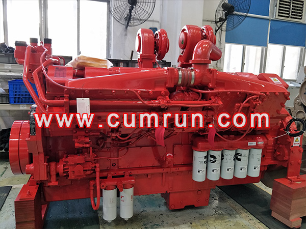
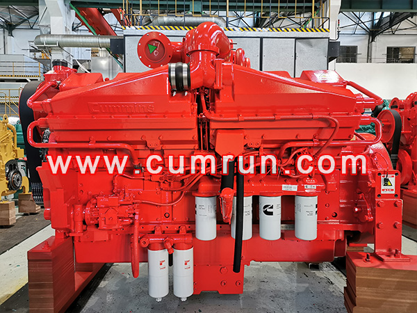
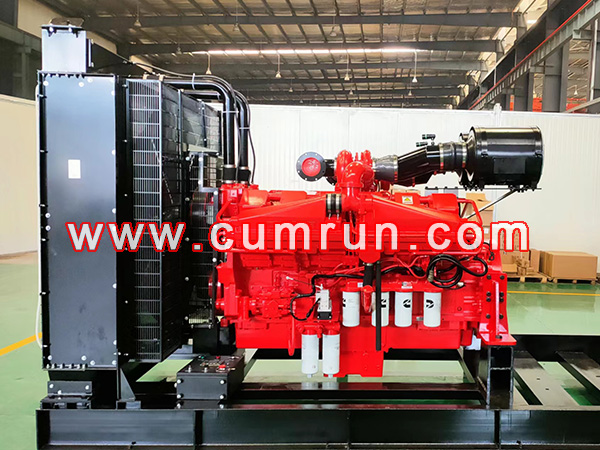
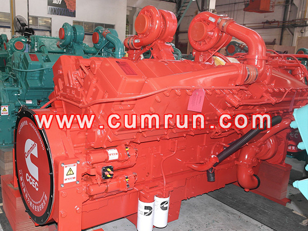
Motor de bomba Cummins KTA50-P1915 1429kw@1500rpm
CATEGORÍA Y ETIQUETAS:Motor de bomba Cummins 1500RPM Descargarconsulta
- Presupuesto
Motor de bomba Cummins KTA50-P1915 1429kw@1500rpm
| La velocidad del motor | Energía en espera | poder principal | Energía continua | |||
| RPM | kWm | BHP | kWm | BHP | kWm | BHP |
| 1500 | 1429 | 1915 | 1200 | 1608 | 1100 | 1475 |
Datos de rendimiento del motor @ 1500 RPM
| POTENCIA DE SALIDA | CONSUMO DE COMBUSTIBLE | |||||
| % | kWm | BHP | kilos/
kWm-h |
libras/
BHP-H |
litro/
hora |
A NOSOTROS. Galones/hora |
| ENERGÍA EN ESPERA | ||||||
| 100 | 1429 | 1915 | 0.206 | 0.338 | 345 | 91.2 |
| PRIMER PODER | ||||||
| 100 | 1200 | 1608 | 0.205 | 0.337 | 289 | 76.3 |
| 75 | 900 | 1206 | 0.210 | 0.346 | 222 | 58.7 |
| 50 | 600 | 804 | 0.220 | 0.362 | 155 | 40.9 |
| 25 | 300 | 402 | 0.233 | 0.383 | 82 | 21.7 |
| POTENCIA CONTINUA | ||||||
| 100 | 1100 | 1475 | 0.206 | 0.339 | 266 | 70.4 |
Cummins Engine Company, Hoja de datos Inc. Engine
FICHA DE DATOS : DS-6243
Modelo de motor : Número de configuración KTA50-P1915 : D283022DX02 Fecha : 5Mar04
Curva de rendimiento : FR-6243 (1PAG / 2l)
FR-6351 (2PAG / 2l)
Número de CPL diagrama de instalación
• Fan a volante (1PAG / 2l): 3170289 • Lista de piezas críticas del motor : 2354
• Fan a volante (2PAG / 2l): 3626419 • Lista de piezas críticas del motor : 2859
DATOS GENERALES DEL MOTOR
Tipo………………………………………………………………………………..4-Ciclo; 60° Vee; 16-Cilindro Diésel
Aspiración ……………………………………………………………. turboalimentado & Baja temperatura. Postenfriado
Diámetro x carrera …………………………………………..— en x en (mm x mm) 6.25 incógnita 6.25 (159 incógnita 159)
Desplazamiento……………………………………………..— en3 (litro) 3067 (50.3)
Relación de compresión……………………………………………………..14.9 : 1
Peso seco
Motor del ventilador al volante……………………………….- libras (kilos) 11820 (5360)
Peso húmedo
Motor del ventilador al volante……………………………………… - libras (kilos) 12485 (5662)
Momento de inercia de componentes giratorios.
• con firmware 6009 Volante ……………………………………… — lbm • pies2 (kilos • m2) 301 (12.7)
• con firmware 6017 Volante………………………………………. — lbm • pies2 (kilos • m2) 515 (21.7)
Centro de gravedad desde la cara trasera de la carcasa del volante (FH 6024) ……………………- en (milímetros) 47.5 (1206)
Centro de gravedad sobre la línea central del cigüeñal …………………………- en (milímetros) 11.0 (279)
Carga estática máxima en el cojinete principal trasero……………………………………………………………….. - libras (kilos) 2000 (908)
MONTAJE DEL MOTOR
Momento flector máximo en la cara posterior del bloque…………………………………………………. — libras • pies (norte·metro) 4500 (6100)
SISTEMA DE ESCAPE
Contrapresión máxima a potencia nominal en espera …………………………………………… — en Hg (mm Hg) 2 (51)
SISTEMA DE INDUCCIÓN DE AIRE
Restricción máxima de aire de admisión
• con elemento filtrante sucio a potencia nominal en espera………………………………………. — en H2O (mmH2O) 25 (635)
• con elemento filtrante limpio a potencia nominal en espera ……………………………………. — en H2O (mmH2O) 15 (381)
SISTEMA DE ENFRIAMIENTO (Se requiere posenfriamiento a baja temperatura; 1 Bomba / 2 Bucle o 2 Bomba / 2 Bucle)
Capacidad de refrigerante: solo motor …………………………………………………. - chica estadounidense (litro) 37 (140)
— Postenfriadores………………………………………………………………………… - chica estadounidense (litro) 9 (34)
Carga estática máxima de refrigerante por encima de la línea central del cigüeñal del motor…………………………………….. — pies (metro) 60 (18.3)
Rango de modulación del termostato: flujo alto (Chaqueta) ………………………….- ° F (°C) 180 – 200 (82 – 93)
Temperatura máxima del tanque superior para energía de reserva / poder principal………………………………. - ° F (°C) 220 / 212 (104 / 100)
Temperatura objetivo de entrada del refrigerante a los posenfriadores @ 77 °F (25 °C) Ambiente- ……………………. °F (°C) 130 (55)
Temperatura máxima del refrigerante a los posenfriadores; Energía en espera / poder principal ……………… - ° F (°C) 160 / 150 (71 / 66)
Adicional 2 Bomba / 2 Requisitos del bucle
Cabezal de fricción máxima del refrigerante externo al motor: flujo alto (Chaqueta)………………. - psi (kPa) 10 (67)
— Flujo bajo (posenfriador)……………………………… - psi (kPa) 5 (35)
Rango de modulación del termostato: flujo bajo (posenfriador) (2PAG / 2l) w/ hx6123.. - ° F (°C) 95 – 105 (35 – 40)
Tapa de presión mínima (para sistemas de refrigeración con menos de 2 metro [6 pie] Cabeza estática) .. - psi (kPa) 10 (67)
Adicional 1 Bomba / 2 Requisitos del bucle
Cabezal de fricción máxima del refrigerante externo al motor: flujo alto (Chaqueta)………………. - psi (kPa) 10 (70)
— Flujo bajo (posenfriador)……………………………… - psi (kPa) 5 (35)
Rango de modulación del termostato: flujo bajo (posenfriador)………………………………. - ° F (°C) 150 – 175 (66 – 79)
Tapa de presión mínima (para sistemas de refrigeración con menos de 2 metro [6 pie] Cabeza estática) .. - psi (kPa) 14 (96)
SISTEMA DE LUBRICACIÓN
Presión de aceite a velocidad de ralentí ……………………………………………… - psi (kPa) 20 (138)
@ Velocidad gobernada………………………………………………………. - psi (kPa) 50 – 70 (345 – 483)
Temperatura máxima del aceite …………………………………………… - ° F (°C) 250 (121)
Capacidad de aceite con OP 6027 Cacerola de aceite : Alto – Bajo…………………….. - chica estadounidense (litro) 47 – 39 (178 – 148)
Capacidad total del sistema (Incluye filtro de derivación) ……………………- chica estadounidense (litro) 54 (204)
SISTEMA DE COMBUSTIBLE
Tipo Sistema de Inyección………………………………………………………Inyección directa Cummins PT
Restricción máxima en la bomba de inyección de combustible PT: con filtro de combustible limpio…………………………………………….. — en Hg (mm Hg) 4.0 (102)
— con filtro de combustible sucio………………………………………………. — en Hg (mm Hg) 8.0 (203)
Altura máxima permitida en la línea de retorno del inyector (Compuesto por cabezal de fricción y cabezal estático.)…………. — en Hg (mm Hg) 6.5 (165)
Flujo máximo de combustible a la bomba de inyección……………………… — Gph de EE. UU. (litro / hora) 151 (570)
SISTEMA ELÉCTRICO
Motor de arranque (Servicio pesado, Compromiso positivo)…………………………………………………………. — voltio 24
Sistema de carga de batería, Tierra negativa……………………— amperio 35
Resistencia máxima permitida del circuito de arranque …………………………. — ohmios 0.002
Capacidad mínima recomendada de la batería
• Remojo en frío @ 50 °F (10 °C) y arriba………………………………… — 0 °F CCA 1280
• Remojo en frío @ 32 °F a 50 °F (0 °C a 10 °C) ………………………… — 0 °F CCA 1800
• Remojo en frío @ 0 °F a 32 °F (-18 °C a 0 °C) ………………………… — 0 °F CCA 1800
CAPACIDAD DE ARRANQUE EN FRÍO
Temperatura ambiente mínima para asistido (con calentador de refrigerante) Arranque en frío dentro 10 artículos de segunda clase………………………….. - ° F (°C) 50 (10)
Temperatura ambiente mínima para arranque en frío sin asistencia ………………………- ° F (°C) 45 (7)
DATOS DE RENDIMIENTO
Todos los datos se basan en: • Motor funcionando con sistema de combustible., bomba de agua, bomba de aceite lubricante, filtro de aire y escape
silenciador; No se incluyen el alternador de carga de batería., admirador, y componentes accionados opcionales.
• Motor funcionando con combustible correspondiente al grado No.. 2-D según ASTM D975.
•ISO 3046, Parte 1, Condiciones de referencia estándar de:
Presión barométrica : 100 kPa (29.53 en Hg) Temperatura del aire : 25 °C (77 °F)
Altitud : 110 metro (361 pie) Humedad relativa : 30%
Banda de estabilidad en estado estacionario con cualquier carga constante ………………….. — % +/- 0.25
Nivel estimado de presión sonora en campo libre de un grupo electrógeno típico;
Excluye ruido de escape; a carga nominal y 7.5 metro (24.6 pie); 1500 rpm…………………………………………… — dBA 92.4
Ruido de escape en 1 m Horizontalmente desde la línea central de la salida del tubo de escape hacia arriba a 45°……………………….— dBA N.A.
Lo anterior es la información técnica general del motor de la bomba Cummins KTA50-P1915. También es para nosotros suministrar las piezas genuinas de Cummins KTA50-P1915 y unidades de motor KTA50-P1915 con bomba de agua (Bomba de fuego)
Motor de bomba Cummins,Unidades de potencia Cummins,Unidades de energía marina Cummins,Camión de bomberos Cummins,Motor de protección contra explosiones Cummins,Distribuidor de motores de bomba Cummins,Agente de motor de bomba Cummins
Formulario de consulta ( Te responderemos lo antes posible. )
Quizás a ti también te guste
Motor de bomba Cummins,Unidades de potencia Cummins,Unidades de energía marina Cummins,Camión de bomberos Cummins,Motor de protección contra explosiones Cummins,Distribuidor de motores de bomba Cummins,Agente de motor de bomba Cummins XML


